
What Are Transmission Towers?
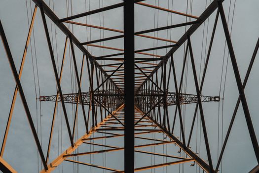
Transmission towers are tall, lattice-steel or monopole structures that support high-voltage overhead power lines. They are the backbone of the electrical grid, carrying electricity from generating stations and substations across long distances to distribution networks that serve homes, businesses, and industry. Without them, modern power transmission at scale would be impossible.
Unlike distribution poles, which typically operate below 69 kV, transmission towers are engineered for voltages ranging from 69 kV to 765 kV and beyond. Their height, spacing, and mechanical design are all determined by voltage class, terrain, span length, and the weight of conductors and hardware.
Why Transmission Towers Matter
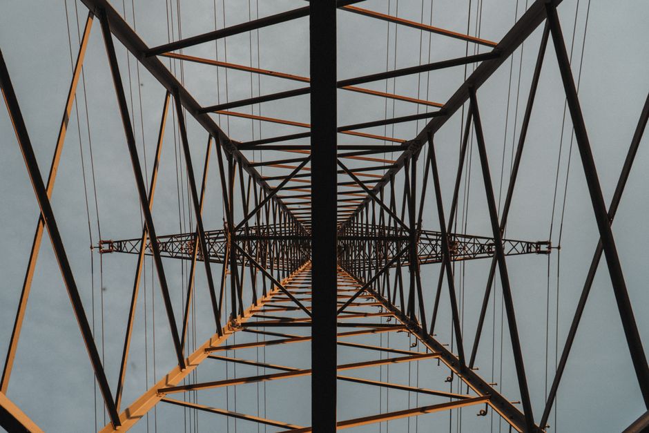
Transmission towers do far more than hold wires in the air. They:
- Maintain safe electrical clearances between conductors and the ground, buildings, and roads
- Withstand wind, ice, seismic, and thermal loads over decades of service
- Enable efficient long-distance power transfer with minimal losses
- Support grid reliability, redundancy, and interconnection between regions
As grids modernize to integrate renewable energy and smart technologies, tower design and materials continue to evolve.
Main Types of Transmission Towers
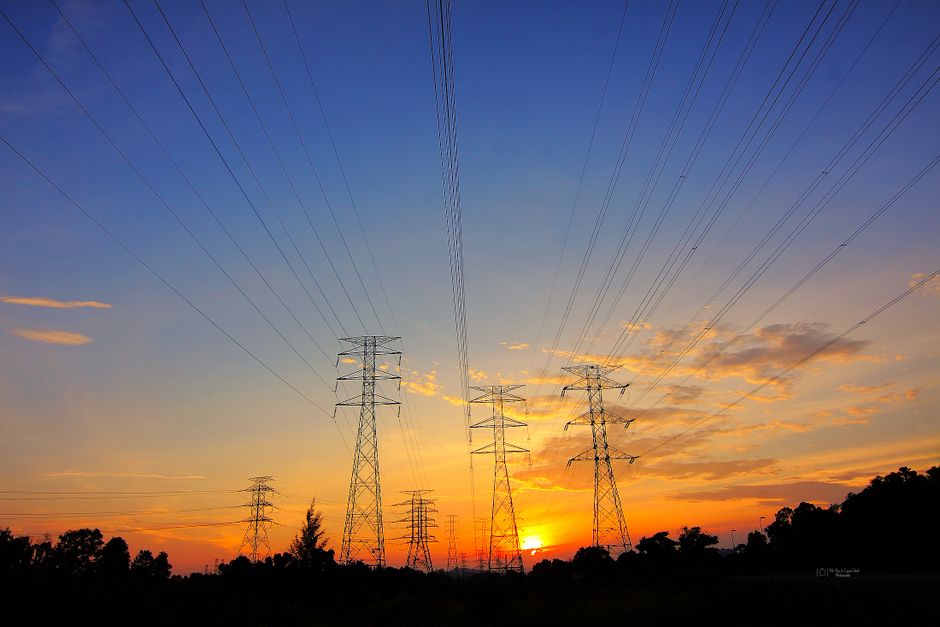
1. Lattice Steel Towers
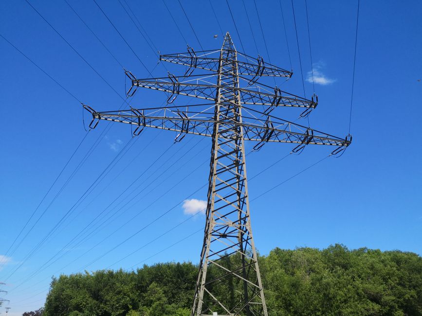
Lattice towers are the most common type worldwide. They consist of steel angle sections bolted or welded into a truss framework. They are strong, relatively lightweight, and can be assembled on site. Lattice towers are used for both suspension and tension applications and are cost-effective for tall, high-voltage structures.
2. Monopole Towers
Monopoles are single tubular steel or concrete poles with a smaller footprint than lattice towers. They are popular in urban and suburban areas because they require less land and have a cleaner appearance. However, they are generally limited to lower heights and voltages compared with lattice designs.
3. Guyed Towers
Guyed towers use tensioned cables (guys) anchored to the ground for stability. They are lighter and less expensive than self-supporting towers but require a larger land area for anchor points. They are common in rural and flat terrain.
4. Wood Pole and H-Frame Structures
For lower transmission voltages (typically 69 kV to 138 kV), wood poles and H-frame structures are still used. They are economical in areas with abundant timber and moderate load requirements.
5. Tubular Steel Poles
Tubular steel poles offer high strength-to-weight ratios and are often used where aesthetics and limited right-of-way are priorities. They can be designed as single or multi-circuit structures.
Functional Classifications
Transmission towers are also classified by their role in the line:
| Type | Function | Typical Use |
|---|---|---|
| Suspension Tower | Supports conductors vertically with insulator strings | Straight sections of line |
| Tension (Dead-End) Tower | Anchors conductors and resists longitudinal loads | Line ends, angles, crossings |
| Transposition Tower | Rotates conductor positions to balance impedance | Long lines to reduce losses |
| Angle Tower | Handles changes in line direction | Route bends |
| Terminal Tower | Connects line to substation equipment | Substation entries |
Key Design and Engineering Facts
- Voltage class: Tower height and insulation increase with voltage. A 765 kV tower can exceed 60 meters.
- Right-of-way: Transmission lines require cleared corridors, often 30–60 meters wide, to prevent vegetation contact.
- Conductor sag: Engineers calculate sag and tension to maintain safe ground clearance under all weather conditions.
- Foundation types: Depending on soil, towers use spread footings, pile foundations, or rock anchors.
- Corrosion protection: Galvanizing, weathering steel, and protective coatings extend tower life to 50 years or more.
- Insulators: Glass, porcelain, or composite insulators isolate conductors from the grounded tower.
Practical Tips for Working With Transmission Towers
- Always verify voltage class and clearance requirements before design or maintenance work.
- Use LiDAR or drone surveys to map terrain and existing infrastructure accurately.
- Coordinate with landowners and regulators early, especially for new right-of-way.
- Inspect towers regularly for corrosion, loose bolts, and foundation movement.
- Consider composite materials and modular designs to reduce installation time.
- Plan for future capacity—upgrading conductors is easier than rebuilding towers.
Transmission Towers and the Future Grid
Modern transmission towers are increasingly designed for higher capacity, compact footprints, and resilience against extreme weather. New materials, smart sensors, and digital twin modeling are helping utilities monitor structural health in real time. As offshore wind, solar farms, and cross-border interconnections expand, transmission towers will remain a critical enabler of a reliable, low-carbon energy system.
Conclusion
Transmission towers are essential infrastructure that quietly powers modern life. Understanding their types, functions, and engineering principles helps utilities, contractors, and policymakers make better decisions about grid expansion and maintenance. Whether it is a lattice tower crossing a mountain range or a monopole lining a city street, each structure plays a precise role in delivering electricity safely and efficiently.