
 English
 简体中文
简体中文 Русский
 Español
 Deutsch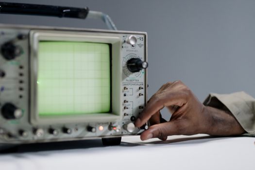
Supply programme
How to Use an Oscilloscope: Beginner's Complete Guide
Learn how to use an oscilloscope with this beginner‘s guide. Master controls, probes, triggering, and measurements. Start measuring like a pro today!
Introduction to Oscilloscopes
An oscilloscope is one of the most powerful diagnostic tools in electronics. It visualizes electrical signals as a graph of voltage over time, allowing you to see waveform shape, amplitude, frequency, and anomalies that a multimeter simply cannot reveal. Whether you are troubleshooting a circuit, designing a new product, or learning electronics, mastering the oscilloscope is a rite of passage. This beginner's guide will walk you through everything you need to know to use an oscilloscope safely and effectively.
What Is an Oscilloscope and Why Do You Need One?
At its core, an oscilloscope (often called a scope) captures electrical signals and displays them on a screen. The vertical axis (Y) represents voltage, and the horizontal axis (X) represents time. This time-domain view is invaluable for:
- Measuring signal amplitude, frequency, and period
- Checking signal integrity and identifying noise or distortion
- Debugging digital circuits, serial protocols, and power supplies
- Analyzing rise time, fall time, and duty cycle
- Comparing multiple signals simultaneously with multi-channel scopes
Unlike a multimeter that gives you a single number, an oscilloscope shows you the whole story of a signal.
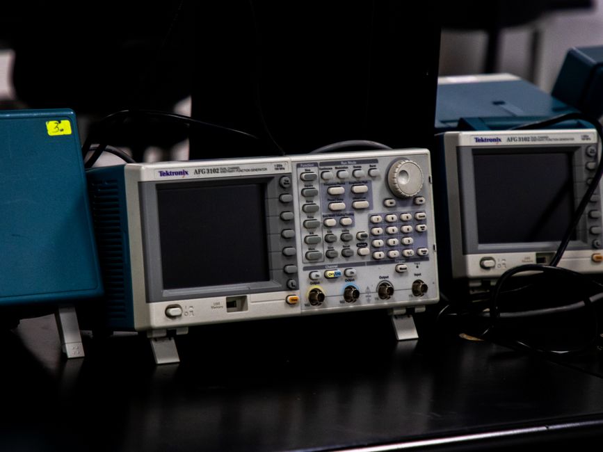
Types of Oscilloscopes
There are several types of oscilloscopes, each suited to different needs and budgets:
| Type | Description | Best For |
|---|---|---|
| Analog Oscilloscope | Uses CRT to display waveforms directly | Legacy equipment, education |
| Digital Storage Oscilloscope (DSO) | Digitizes and stores waveforms | General electronics, advanced analysis |
| Mixed Signal Oscilloscope (MSO) | Combines analog and digital channels | Embedded systems, digital debugging |
| PC-Based Oscilloscope | Uses a computer for display and control | Portable setups, budget projects |
| Handheld Oscilloscope | Battery-powered, rugged design | Field service, mobile troubleshooting |
For beginners, a Digital Storage Oscilloscope (DSO) with at least two channels and a bandwidth of 50–100 MHz is a great starting point.
Understanding Key Specifications
Before you buy or use an oscilloscope, it's essential to understand its specifications:
- Bandwidth: The maximum frequency the scope can accurately measure. Rule of thumb: choose a bandwidth at least 5 times the highest frequency you expect to measure.
- Sample Rate: How many samples per second the scope takes. Higher is better; aim for at least 5 times the bandwidth.
- Channels: Number of signals you can display simultaneously. Two channels are standard; four are better for complex work.
- Memory Depth: How many samples can be stored. Deeper memory allows capturing longer time windows at high resolution.
- Vertical Resolution: Typically 8 bits, determining how precisely voltage is measured.
Getting Started: Basic Controls and Interface
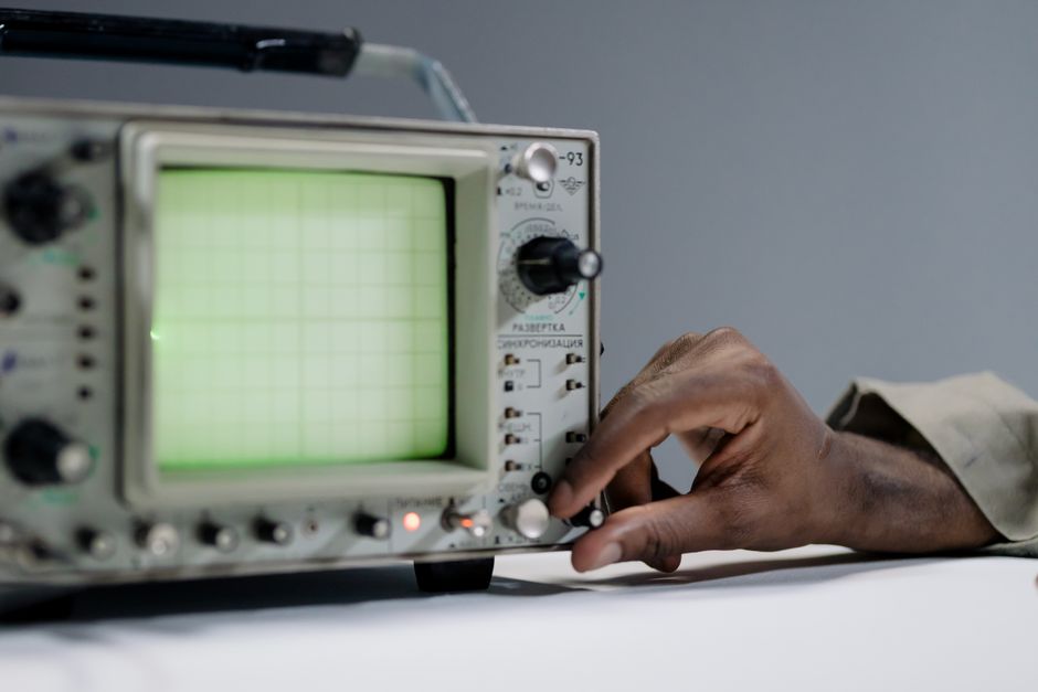
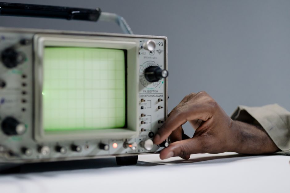
When you first power on your oscilloscope, you'll see a screen with grid lines (graticule) and a variety of knobs and buttons. Here's a quick tour:
Front Panel Controls
- Vertical Section: Controls per channel—volts/div knob adjusts amplitude scaling, and position knob moves the trace up or down.
- Horizontal Section: Time/div knob sets the time scale, and position knob shifts the waveform left or right.
- Trigger Section: Determines when the scope starts capturing. Level knob sets the trigger threshold, and trigger mode selects auto, normal, or single.
- Menu Buttons: Soft keys that change function based on on-screen menus.
- Input Connectors: BNC connectors for probes, plus a ground terminal.
Probes and Compensation
Oscilloscope probes are not just wires—they are precision instruments. Most scopes come with switchable 1X/10X passive probes. The 10X setting reduces circuit loading and extends bandwidth. Always compensate your probe before use: connect it to the probe compensation terminal and adjust the trimmer until the square wave looks flat.
Step-by-Step: How to Use an Oscilloscope
Step 1: Safety First
Never connect the oscilloscope ground clip to a live circuit point that isn't ground. The scope's ground is connected to earth ground, and improper grounding can cause short circuits or damage. Use an isolation transformer or differential probe when measuring floating circuits.
Step 2: Connect the Probe
Attach the probe to Channel 1 (CH1). Set the probe to 10X and connect the ground clip to the circuit ground. Touch the probe tip to the test point.
Step 3: Set Up the Display
Press the Auto Set button if available—this automatically adjusts volts/div, time/div, and trigger. If not, manually set:
- Volts/div to a level that keeps the waveform on screen
- Time/div to show 2–3 cycles of the signal
- Trigger to edge mode, rising edge, and adjust level until the waveform is stable
Step 4: Measure the Signal
Use the scope's measurement menus to read frequency, period, peak-to-peak voltage, RMS, rise time, and more. Cursors can also be used for manual measurements.
Step 5: Analyze and Interpret
Look for anomalies: ringing, overshoot, noise, clipping, or glitches. Compare expected vs. actual waveforms to diagnose issues.
Essential Triggering Techniques
Triggering is what makes an oscilloscope useful—it stabilizes the display. Common trigger modes:
- Auto: Scope free-runs if no trigger occurs. Good for general viewing.
- Normal: Scope only updates when a trigger occurs. Best for catching rare events.
- Single: Captures one event then stops. Ideal for one-shot signals.
Advanced triggers include pulse width, video, and serial protocol triggers, which help isolate specific events.
Common Measurements and What They Mean
| Measurement | Description | Typical Use |
|---|---|---|
| Vpp (Peak-to-Peak) | Voltage difference between highest and lowest points | Signal amplitude |
| Frequency | Cycles per second | Clock signals, oscillators |
| Period | Time for one cycle | Timing analysis |
| Duty Cycle | Percentage of time signal is high | PWM, digital signals |
| Rise Time | Time to go from 10% to 90% of amplitude | Signal integrity |
Practical Tips for Beginners
- Always start with the probe on 10X to minimize circuit loading.
- Use the Auto Set button as a starting point, then refine manually.
- Keep ground leads short to avoid picking up noise.
- Practice on a known signal, like the probe compensation output, before probing live circuits.
- Learn to use cursors for precise voltage and time measurements.
- Take screenshots or save waveforms for documentation.
Common Mistakes to Avoid
- Forgetting to compensate the probe, leading to distorted readings.
- Setting volts/div too high or too low, causing the waveform to be off-screen or too small.
- Using a ground clip on a non-ground point, risking short circuits.
- Ignoring bandwidth limitations—signals above the scope's bandwidth will be attenuated and distorted.
- Not using triggering correctly, resulting in an unstable display.
Conclusion
Using an oscilloscope may seem daunting at first, but with practice, it becomes second nature. Start with simple signals, learn your scope's controls, and gradually tackle more complex measurements. The oscilloscope is your window into the invisible world of electronics—master it, and you'll unlock a deeper understanding of how circuits truly behave. Remember to always prioritize safety, and don't be afraid to experiment. Happy measuring!
Instruments in scope
Browse all Models frequently quoted with this programme
Keep reading
Other supply programmes
10 Best Testing Instruments for Electrical Engineers 2025 Discover the 10 best testing instruments for electrical engineers in 2025. Compare multimeters, insulation testers, thermal cameras, and more. Upgrade your toolkit today! View solution Fluke vs Keysight Multimeters: Which to Buy? Compare Fluke vs Keysight multimeters: accuracy, safety, features, and price. Find out which brand is best for your needs. Read our guide now! View solution How to Calibrate a Digital Multimeter: Step-by-Step Learn how to calibrate a digital multimeter step by step. Covers equipment, DC/AC voltage, resistance, current, tolerance checks, and documentation. Start now! View solution How to Use an Oscilloscope: Beginner's Complete Guide Learn how to use an oscilloscope with this beginner‘s guide. Master controls, probes, triggering, and measurements. Start measuring like a pro today! View solution
Start a programme like this
Send the channel you sell into, the measurement jobs you cover and your annual volume.