English
 简体中文
简体中文 Русский
 Español
 Deutsch

Automatic Transfer Switch Wiring Diagram Made Simple
Learn automatic transfer switch wiring diagram basics: inputs, control terminals, grounding, and step-by-step installation tips. Read the full guide now!

Understanding the Automatic Transfer Switch
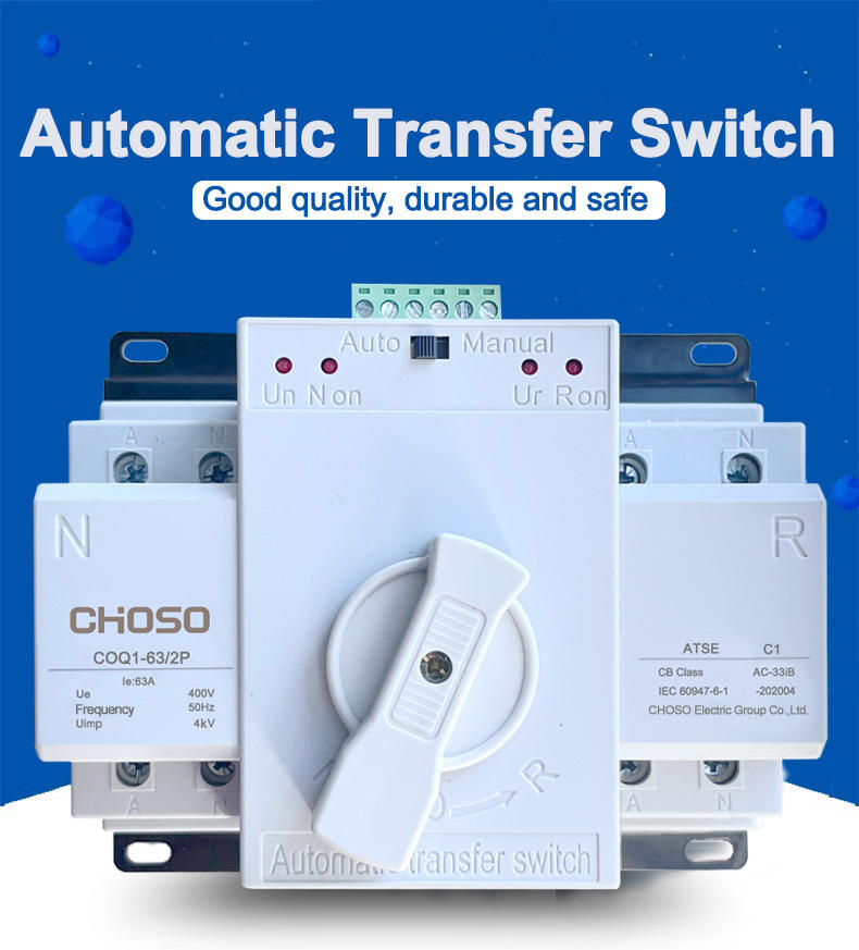
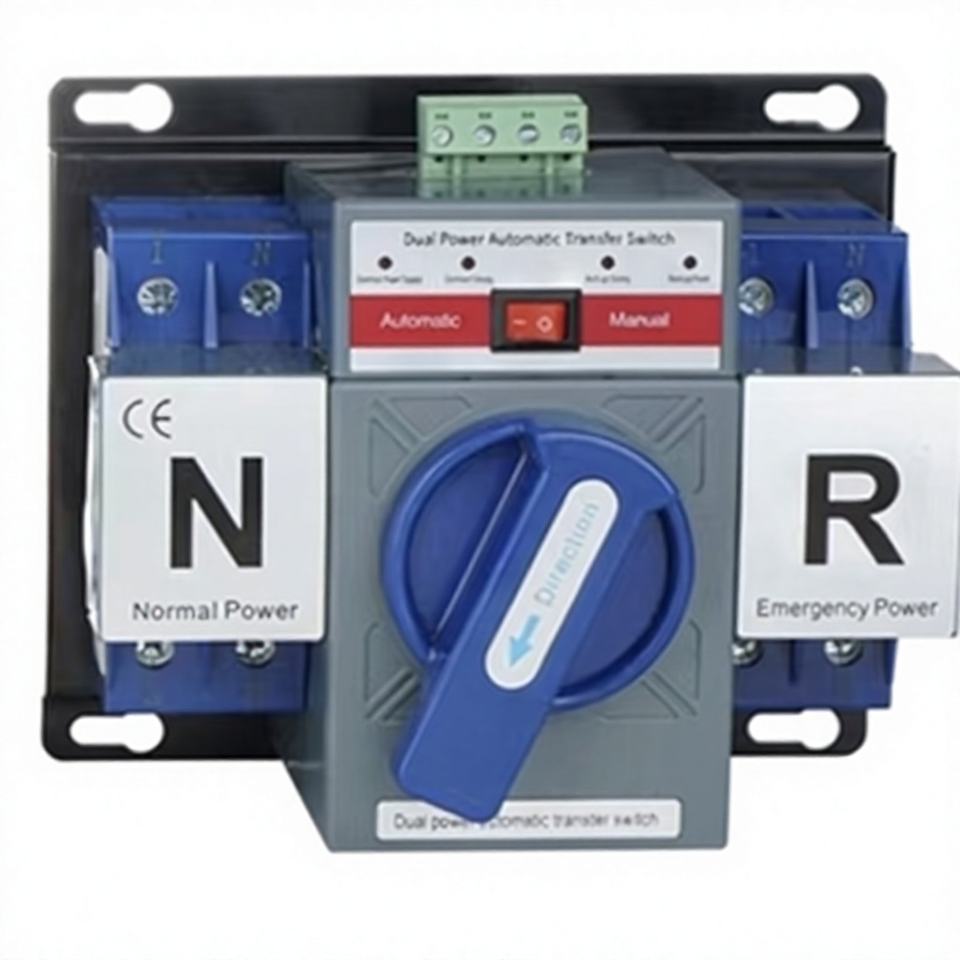
An automatic transfer switch (ATS) is one of the most important safety devices in any backup power system. It monitors the incoming utility power and, when an outage occurs, automatically switches the electrical load to a backup generator. When utility power returns, the ATS switches the load back and shuts down the generator. Understanding the wiring diagram is the first step toward a safe, code-compliant installation.
This guide breaks down the automatic transfer switch wiring diagram into simple, digestible sections so that electricians, facility managers, and informed homeowners can read, plan, and troubleshoot an ATS installation with confidence.
What an ATS Wiring Diagram Shows
A proper ATS wiring diagram typically includes:
- Utility (normal) power source conductors
- Generator (emergency) power source conductors
- Load distribution conductors
- Control wiring for sensing and switching
- Neutral and ground connections
- Terminal block and lug identification
Key Components in the Wiring Diagram
1. Power Inputs
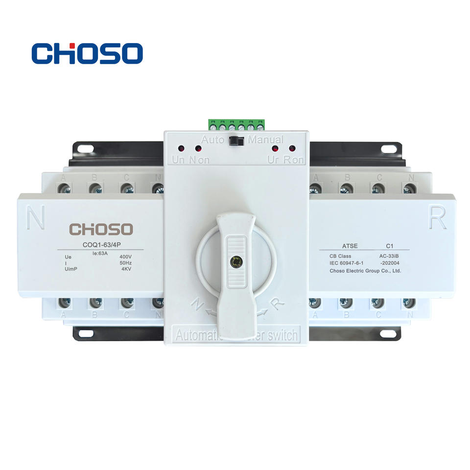
Every ATS has two power inputs: the normal source (utility) and the emergency source (generator). In the diagram, these are usually labeled N1, N2, N3 for the normal side and E1, E2, E3 for the emergency side. For single-phase systems, you will see L1 and L2 plus a neutral. For three-phase systems, L1, L2, L3, and neutral are shown.
2. The Switching Mechanism
The transfer mechanism is either a contactor-based or breaker-based design. The diagram shows mechanically interlocked contacts that prevent both sources from connecting to the load at the same time. This interlock is a critical safety feature that prevents backfeeding the utility lines.
3. Control and Sensing Terminals
Control terminals connect the ATS to the generator's start circuit and to the utility sensing circuit. Typical terminals include:
- T1 and T2: utility voltage sensing
- 1 and 3: generator start contacts (dry contacts)
- B+ and B-: DC control power for the transfer switch
- Auxiliary contacts for remote indication
4. Neutral and Ground Bars
The diagram clearly separates the neutral bar from the equipment ground bar. In a service-entrance rated ATS, the neutral may be bonded to ground; in a sub-panel application, the neutral and ground must remain isolated. Always confirm the bonding configuration for your specific installation.

Step-by-Step Wiring Overview
Step 1: Mount and Prepare
Mount the ATS near the utility meter and main panel, following local code and manufacturer clearance requirements. Remove knockouts and install conduit as shown in the diagram.
Step 2: Connect the Utility Feed
Run the utility service conductors to the normal input lugs. Torque all lugs to the specification printed on the label—typically 45 to 75 inch-pounds for larger conductors.
Step 3: Connect the Generator Feed
Route the generator output conductors to the emergency input lugs. Keep generator control wiring in a separate conduit from power conductors to reduce electrical noise.
Step 4: Connect the Load
Connect the load conductors to the load lugs. These feed the main distribution panel or a dedicated essential-loads panel.
Step 5: Wire the Control Circuit
Connect the two-wire generator start circuit to the appropriate terminals. Connect utility sensing leads to the normal source. If the ATS uses a battery charger, wire it to a dedicated circuit.
Step 6: Bond and Ground
Follow the diagram for grounding electrode conductor and equipment grounding conductor terminations. Never omit the ground connection.
Reading a Typical Wiring Diagram Table
| Terminal | Function | Typical Wire |
|---|---|---|
| N1, N2, N3 | Normal (utility) input | Service conductors |
| E1, E2, E3 | Emergency (generator) input | Generator output |
| T1, T2 | Utility sensing | 14–12 AWG control |
| 1, 3 | Generator start contacts | 16–14 AWG |
| L1, L2, L3 | Load output | Panel feeders |
| GND | Equipment ground | Per NEC Table 250.122 |
Common Wiring Mistakes to Avoid
- Reversing normal and emergency inputs: This can energize the utility side from the generator and create a lethal backfeed hazard.
- Omitting the neutral isolation: In sub-panel applications, bonding neutral and ground creates parallel paths and nuisance tripping.
- Undersized control wire: Long control runs cause voltage drop and unreliable generator starting.
- Skipping torque specs: Loose lugs overheat and fail under load.
- Ignoring the interlock: Never bypass the mechanical interlock for convenience.
Testing After Wiring
After completing the wiring, perform a full functional test:
- Verify all terminations are tight and correctly labeled.
- Simulate a utility outage by opening the normal source breaker.
- Confirm the generator starts and the ATS transfers within the designed time delay.
- Restore utility power and confirm the ATS returns to normal and the generator cools down and shuts off.
- Record the results in your maintenance log.
Practical Tips for a Smooth Installation
- Always photograph the existing wiring before you begin.
- Label every conductor on both ends.
- Use a wiring diagram specific to your ATS model—generic diagrams can mislead.
- Keep the manufacturer's manual on site during installation.
- Confirm the ATS ampacity matches the service and generator rating.
- Check local code for required disconnect and signage.
Conclusion
An automatic transfer switch wiring diagram does not have to be intimidating. By understanding the two power inputs, the interlocked switching mechanism, the control terminals, and the grounding requirements, you can plan and execute a safe installation. Always follow the manufacturer's diagram, respect the mechanical interlock, and test thoroughly before putting the system into service. When in doubt, consult a licensed electrician—safety always comes first.
Send the load list and utility/generator data — we propose switch ratings, transition type and enclosure.