Introduction to Resistance Measurement
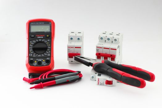
Measuring resistance is one of the most fundamental tasks you can perform with a multimeter. Whether you're troubleshooting a faulty circuit, checking a resistor's value, or verifying continuity, knowing how to measure resistance correctly is an essential skill for anyone working with electronics. In this guide, we'll walk you through the entire process—from selecting the right multimeter to interpreting your readings—so you can measure resistance with confidence and accuracy.
Understanding Resistance and Why It Matters
Resistance, measured in ohms (Ω), is the opposition to the flow of electric current. Every material has some resistance, but components called resistors are designed to provide a specific, predictable resistance value. Measuring resistance helps you:
- Verify that a resistor is within its tolerance range
- Detect open circuits (infinite resistance) or short circuits (near-zero resistance)
- Check continuity of wires, fuses, and switches
- Test sensors, thermistors, and other resistive devices
- Troubleshoot PCBs and identify damaged components
Without accurate resistance measurements, diagnosing electrical problems becomes guesswork. A reliable multimeter and proper technique are your best tools.
Choosing the Right Multimeter
Not all multimeters are created equal. For resistance measurements, consider these factors:
Digital vs. Analog Multimeters
Digital multimeters (DMMs) are preferred for resistance measurement because they display exact numerical values, are easy to read, and typically have high input impedance. Analog multimeters can also measure resistance but require interpreting a needle position on a nonlinear scale, which is less precise.
Key Specifications
- Resolution: The smallest change in resistance the meter can display (e.g., 0.1 Ω).
- Accuracy: How close the reading is to the true value, often expressed as a percentage.
- Range: The maximum resistance measurable (e.g., 40 MΩ).
- Auto-ranging: Automatically selects the best range for the resistance being measured.
For general electronics work, a DMM with at least 0.1 Ω resolution and a 40 MΩ range is sufficient. For precision work, consider a bench multimeter with higher accuracy.
Safety Precautions Before You Measure
Resistance measurements are generally safe, but you must follow these precautions to avoid damaging your meter or injuring yourself:
- De-energize the circuit: Always turn off power and disconnect the circuit from any power source before measuring resistance. The multimeter supplies its own small test current, and external voltage can damage the meter.
- Discharge capacitors: Large capacitors can hold a dangerous charge even after power is removed. Discharge them with a resistor before testing.
- Isolate the component: For accurate readings, at least one leg of the component should be desoldered or lifted from the circuit to prevent parallel paths from affecting the measurement.
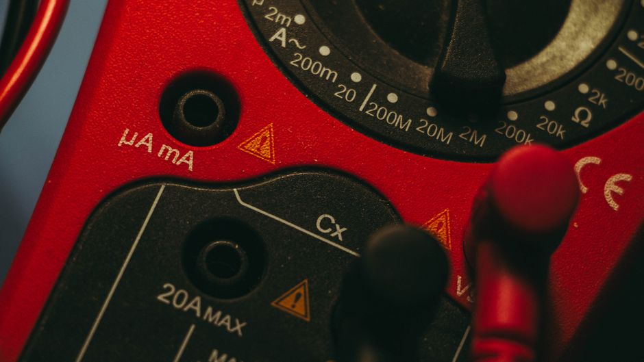
- Use the correct jacks: Plug the black probe into the COM jack and the red probe into the VΩmA jack (or as indicated for resistance).
Step-by-Step: How to Measure Resistance
Step 1: Prepare the Multimeter
Insert the black probe into the COM terminal and the red probe into the terminal marked with Ω (often shared with V and mA). Rotate the dial to the resistance setting (Ω). If your meter is not auto-ranging, select the highest range first, then adjust downward for better resolution.
Step 2: Check the Probes
Touch the probe tips together. The display should read a very low resistance, typically between 0.1 Ω and 0.5 Ω. This is the resistance of the leads themselves. If the reading is unstable or much higher, replace the probes or check for internal fuse issues.
Step 3: Isolate the Component
As mentioned, disconnect at least one end of the component from the circuit. This ensures you're measuring only the component and not other parallel resistances.
Step 4: Connect the Probes
Touch the probe tips to the two ends of the component. Polarity doesn't matter for resistance. Make sure your fingers don't touch both probe tips simultaneously, as your body resistance could parallel the component and skew the reading.
Step 5: Read and Interpret the Display
Wait for the reading to stabilize. Note the value and unit (Ω, kΩ, MΩ). Compare it to the expected value. For resistors, check the color code or marked value and consider the tolerance (e.g., ±5%).
Step 6: Measure Continuity (Optional)
Many multimeters have a continuity mode (often indicated by a diode or sound wave symbol). In this mode, the meter beeps if resistance is below a threshold (typically 50 Ω or less). This is perfect for checking fuses, wires, and switches.
Interpreting Resistance Readings
| Reading | Meaning | Possible Action |
|---|
| 0 Ω or very low | Short circuit or closed switch | Check for unintended connections; if testing a switch, it's working. |
| Expected value ± tolerance | Component is good | No action needed. |
| Much higher than expected | Component may be degraded or open | Replace component; check for poor solder joints. |
| OL (overload) or infinite | Open circuit | Check for broken wire, blown fuse, or open resistor. |
| Fluctuating reading | Loose connection or unstable component | Reseat probes; check solder joints; component may be faulty. |
Common Mistakes and How to Avoid Them
- Measuring in-circuit: Parallel paths can give false low readings. Always isolate the component.
- Touching both probes: Your body resistance (often 100 kΩ–1 MΩ) can affect high-resistance measurements. Hold probes by the insulated handles.
- Using the wrong range: On manual-ranging meters, a range that's too low will show OL; too high reduces resolution.
- Forgetting lead resistance: For low-resistance measurements (under 10 Ω), subtract the lead resistance or use a 4-wire Kelvin setup.
- Measuring a live circuit: This can damage the meter and give erroneous readings. Always power down.
Advanced Tips for Accurate Measurements
Use a 4-Wire Kelvin Measurement
For very low resistances (e.g., motor windings, PCB traces), a 2-wire measurement includes lead and contact resistance. A 4-wire Kelvin setup uses separate current and sense leads to eliminate these errors, providing readings accurate to milliohms.
Temperature Compensation
Resistance of most materials changes with temperature. For critical measurements, note the ambient temperature and, if necessary, use a temperature-compensated multimeter or apply correction factors.
Shielding and Noise
High-resistance measurements (above 1 MΩ) are susceptible to noise and stray currents. Keep leads short, use shielded cables, and avoid touching the component.
Frequently Asked Questions
Can I measure resistance with the circuit powered on?
No. Never measure resistance on a live circuit. The multimeter's internal battery provides the test current, and external voltage will corrupt the reading and may damage the meter.
Why does my multimeter show OL?
OL stands for overload, meaning the resistance is higher than the selected range or the circuit is open. Try a higher range if available, or check for a broken connection.
How do I measure a resistor's value if it's soldered in a board?
You can get a rough reading, but for accuracy, desolder one leg. In-circuit measurements are often lower than the actual value due to parallel paths.
What is the difference between resistance and continuity?
Continuity is a quick check for a complete path, usually with an audible beep. Resistance mode gives a precise ohm value. Continuity is faster for go/no-go testing.
Conclusion
Measuring resistance with a multimeter is a skill that improves with practice. By following the steps outlined in this guide—preparing your meter, isolating the component, and interpreting readings correctly—you'll be able to diagnose circuits and verify components with confidence. Remember to always prioritize safety, use the right range, and be aware of common pitfalls. With these techniques, your multimeter will become an indispensable tool in your electronics toolkit.

 English
 简体中文
简体中文 Русский
 Español
 Deutsch